Regardless of the computer or operating system, standard (“IBM-compatible”) desktop PCs and laptops all power on and start up using one of two ways: the traditional BIOS-MBR method and the newer UEFI-GPT method, used by the latest versions of Windows, Linux, and Mac OS X on newer PCs, laptops, and tablets. This article summarizes the process by which traditional BIOS PCs load an operating system, covering the basics and details of the BIOS, MBR, and bootsector.
This article has been unofficially dubbed Everything you ever wanted to know about how your PC boots, part one.
Contents
Overview of the BIOS/MBR Boot Process
In the diagram below, the boot sequence for all standard computers and operating systems is shown:
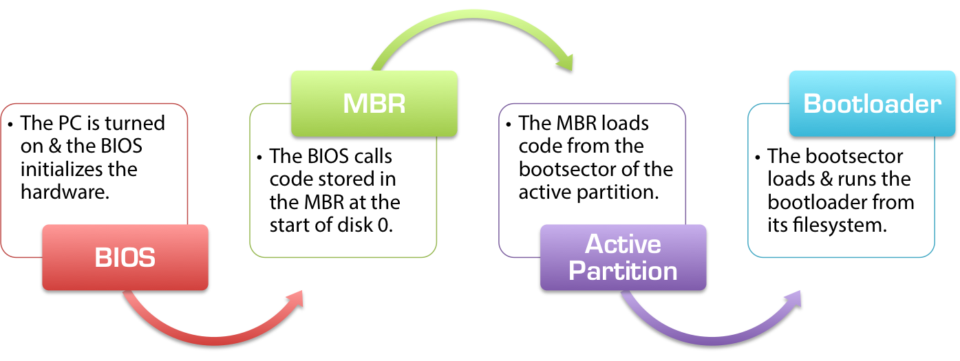
As you can see, the boot process is broken down into several major components, each of which is a completely-separate subsystem with many different options and variations. The implementations of each component can differ greatly depending on your hardware and operating system, but the rules they follow and the process by which they work are always the same.
Components of the Boot Process
The BIOS
The BIOS is where hardware meets software for the first time, and where all the boot magic begins. The BIOS code is baked into the motherboard of your PC, usually stored on what is called an EEPROM 1 and is considerably hardware-specific. The BIOS is the lowest level of software that interfaces with the hardware as a whole,2 and is the interface by means of which the bootloader and operating system kernel can communicate with and control the hardware. Through standardized calls to the BIOS (“interrupts” in computer parlance), the operating system can trigger the BIOS to read and write to the disk and interface with other hardware components.
When your PC is first powered up, a lot happens. Electrical components of the PC are initially responsible for bringing your computer to life, as debouncing circuits take your push of the power button and trigger a switch that activates the power supply and directs current from the PSU to the motherboard and, mainly through it, to all the various components of your PC. As each individual component receives life-giving electricity, it is powered up and brought online to its initial state. The startup routines and overall functionality of the simpler components like the RAM and PSU is hardwired into them as a series of logic circuits (AND/NAND and OR/NOR gates), while more complicated parts such as the video card have their own microcontrollers that act as mini-CPUs, controlling the hardware and interfacing with the rest of your PC to delegate and oversee the work.
The POST Process
Once your PC has been powered on, the BIOS begins its work as part of the POST (Power-On Self Test) process. It bridges all the various parts of your PC together, and interfaces between them as required, setting up your video display to accept basic VGA and show it on the screen, initializing the memory banks and giving your CPU access to all the hardware. It scans the IO buses for attached hardware, and identifies and maps access to the hard disks you have connected to your PC. The BIOS on newer motherboards is smart enough to even recognize and identify USB devices, such as external drives and USB mice, letting you boot from USB sticks and use your mouse in legacy software.
During the POST procedure, quick tests are conducted where possible, and errors caused by incompatible hardware, disconnected devices, or failing components are often caught. It’s the BIOS that’s responsible for a variety of error messages such as “keyboard error or no keyboard present” or warnings about mismatched/unrecognized memory. At this point, the majority of the BIOS’ work has completed and it’s almost ready to move on to the next stage of the boot process. The only thing left is to run what are called “Add-On ROMs”: some hardware attached to the motherboard might require user intervention to complete its initialization and the BIOS actually hands off control of the entire PC to software routines coded into hardware like the video card or RAID controllers. They assume control of the computer and its display, and let you do things like set up RAID arrays or configure display settings before the PC has even truly finished powering up. When they’re done executing, they pass control of the computer back to the BIOS and and the PC enters a basic, usable state and is ready to begin.
BIOS Boot Handoff
After having configured the basic input and output devices of your PC, the BIOS now enters the final stages where it’s still in control of your computer. At this point, you’ll normally be presented with an option to quickly hit a key to enter the BIOS setup from where you can configure hardware settings and control how your PC boots. If you choose nothing, the BIOS will begin the first step in actually “booting” your PC using the default settings.
Earlier we mentioned that an important part of the BIOS’ work is to detect and map connected hard disks. This list now comes in handy, as the BIOS will load a very small program from the first hard disk to the memory and tell the CPU to execute its contents, handing off control of the computer to whatever is on the hard drive and ending its active role in loading your PC. This hard drive is known as “the boot device,” “startup disk,” or “drive 0” and can usually be picked or set in the BIOS setup.
The Boot Device
Regardless of whether the BIOS was configured to boot from a local hard disk or from a removable USB stick, the handoff sequence is the same. Once the BIOS POST and AddOn ROM procedures have completed, the BIOS loads the first 512 bytes from the hard drive of the selected boot device – these 512 bytes are what is commonly known as the MBR, or the Master Boot Record.
The Master Boot Record (MBR)
The MBR is the first and most important component on the software side of things in the boot procedure on BIOS-based machines. Every hard disk has an MBR, and it contains several important pieces of information.
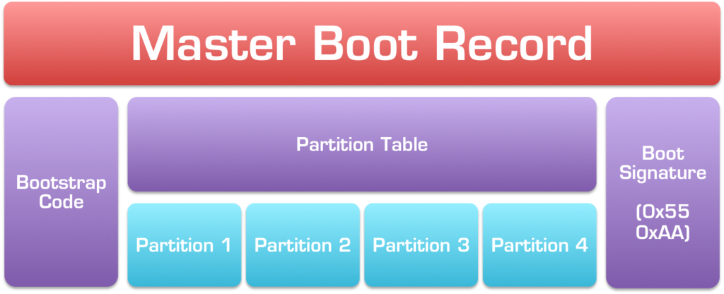
The Partition Table
First and foremost, the MBR contains something called the partition table, which is an index of up to four partitions that exist on the same disk, a table of contents, if you will. Without it (such as on floppy disks), the entire disk could only contain one partition, which means that you can’t have things like different filesystems on the same drive, which in turn would mean you could never install Linux and Windows on the same disk, for example.
Bootstrap Code
Secondly, the MBR also contains a very important bit of code known as the “bootstrap code.” The first 4403 of these 512 bytes can contain literally anything – the BIOS will load it and execute its contents as-is, kicking off the bootloader procedure. 440 bytes is incredibly small. How small? Well, to put things in context, 440 bytes is only 0.3% of the capacity of an ancient 1.44 MiB floppy disk – barely enough to fit any form of useful code – and way, way too small to do something as complicated as call up the operating system kernel from the disk.
Given how tiny the bootstrap code section of the MBR is, the only useful purpose it can really serve is to look up another file from the disk and load it to perform the actual boot process. As such, this bootstrap code is often termed a “stage one bootloader.” Depending on the operating system, the exact place the bootstrap code searches for the “stage 2 bootloader” can change, but on Windows the stage 1 bootloader will search the partition table of the MBR for a partition marked as “active” which is MBR-speak for “bootable,” indicating that the start of the partition contains the next portion of the boot code in its starting sectors (also known as its “bootsector”). On a correctly-created MBR disk, only one partition can be marked as active at a time.4
So the job of the bootstrap code segment in the MBR is pretty simple: look up the active partition from the partition table, and load that code into the memory for execution by the CPU as the next link in the boot chain. Depending on the OS you’re loading, it might actually look up a hard-coded partition instead of the active partition (e.g. always load the bootsector of the 3rd partition) and the offset of the boot code within the partition bootsector might change (e.g. instead of being the first 2 KiB of the partition, it might be the second KiB or 6 KiB starting from the 2nd multiple of the current phase of the moon) – but the basic concept remains the same. However, for legacy compatibility reasons, the MBR almost always loads the first sector of the active partition, meaning another only-512 bytes.
Boot Signature
On IBM-compatible PCs (basically, everything) the final two bytes of the 512-byte MBR are called the boot signature and are used by the BIOS to determine if the selected boot drive is actually bootable or not. On a disk that contains valid bootstrap code, the last two bytes of the MBR should always be 0x55 0xAA.5If the last two bytes of the MBR do not equal 0x55 and 0xAA respectively, the BIOS will assume that the disk is not bootable and is not a valid boot option – in this case, it will fall back to the next device in the boot order list (as configured in the BIOS setup). For example, if the first boot device in the BIOS is set as the USB stick and the second is the local hard disk, if a USB stick without the correct boot signature is plugged in, the BIOS will skip it and move on to attempt to load from the local disk. If no disk in the boot device list has the correct 0x55 0xAA boot signature, the BIOS will then display an error such as the infamous “No boot device is available” or “Reboot and select proper boot device.”
The Partition Boot Sector
As covered above, the bootstrap code in the MBR will usually load a sequence of bytes from the start of the active partition. The exact layout of a partition depends what filesystem the partition has been created or formatted with, but generally looks something like this:
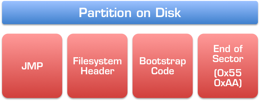
Again, depending on the OS and filesystem, the exact layout of the partition will certainly differ. But this represents a close approximation to what you’ll normally see:
- A single JMP (jump) instruction, which is the assembly6 equivalent of a goto command.
- The filesystem header, which will contain information specific to and important for the filesystem itself.
- Another bootstrap code segment, containing the next stage of the bootloader process.
- An end-of-sector marker, very similar to the 0x55 0xAA boot signature we saw earlier in the MBR.
This is all usually packed into the first sector of the partition, which is normally again only 512 bytes long, and again, can’t fit too much data or instructions. On modern filesystems for newer operating systems, the bootstrap code can take advantage of enhanced BIOS functionality to read and execute more than just 512 bytes, but in all cases, the basic steps remain the same:
- The MBR loads the first 512 bytes of the active partition into the memory and instructs the CPU to execute them.
- The very first (three) bytes of the partition bootsector contain a single JMP instruction, telling the CPU to skip xx bytes ahead and execute the next stage of the bootloader from there.
- The CPU follows the JMP instruction and seeks to the beginning of the bootstrap code contained within the partition bootsector, and starts to execute.
The bootstrap code in the partition is not the end of the road, it’s only another step along the way. Because of how little space is allocated for the bootstrap code in the partition bootsector, the code it contains normally ends with another JMP command instructing the CPU to jump to the next sector in the partition, which is often set aside for the remainder of the partition code. Depending on the filesystem, this can be several sectors in length, or however long it needs to be to fit this stage of the bootloader.
The second-stage bootloader
The second stage of the bootloader, stored in the partition bootsector in the bootstrap section and, optionally, continuing beyond it, carries out the next step in the bootloader process: it looks up a file stored on the partition itself (as a regular file), and tells the CPU to execute its contents to begin the final part of the boot process.
Unlike the previous bootstrap segments of the MBR and the partition bootsector, the next step in the boot process is not stored at a dedicated offset within the partition (i.e. the bootstrap code can’t just tell the CPU to JMP to location 0xABC and execute the boot file from there) – it’s a normal file stored amongst other normal files in the filesystem on the disk.
This significantly more-complicated bootstrap code must actually read the table-of-contents for the filesystem on the partition,7 The second-stage bootloader from older versions of file systems oftentimes placed complicated restrictions on the bootloader files they needed to load, such as requiring them to appear in the first several kilobytes of the partition or being unable to load non-contiguously allocated files on the partition. This file is the last piece of the bootloader puzzle, and there are usually no restrictions as to its size or contents, meaning it can be as large and as complicated as it needs to be to load the operating system kernel from the disk and pass on control of the PC to the OS.
The Bootloader
The actual bootloader files on the disk form the final parts of the boot loading process. When people talk about bootloaders and boot files, they are often referring to this final, critical step of the boot process.
Once control of the PC has been handed-off from the BIOS to the bootstrap code in the MBR and from the MBR to the bootstrap code in the partition bootsector, and from there there to the executable boot files on the active partition, the actual logic involved in determining which operating system to load, where to load it from, which parameters/options to pass on to it, and completing any interactions with the user that might be available, the actual process of starting the operating system begins.
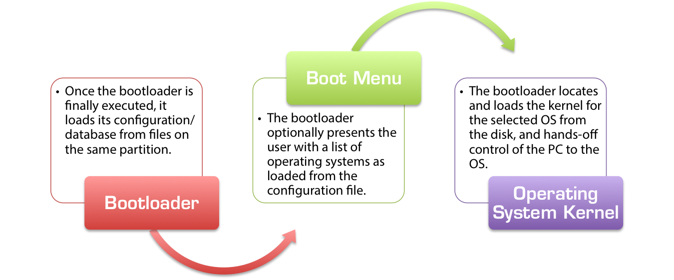
Boot Configuration Files
While the executable bootloader files could theoretically contain hard-coded information pertaining to the operating systems to be loaded from the disk, that wouldn’t be very useful at all. As such, almost all bootloaders separate the actual, executable bootloader from the configuration file or database that contains information about the operating system(s) to load. All of the major bootloaders mentioned below have support for loading multiple operating systems, a process known as “dual-booting” or “multi-booting.”
Popular Bootloaders
As discussed previously, there are many different bootloaders out there. Each operating system has its own bootloader, specifically designed to read its filesystem and locate the kernel that needs to be loaded for the OS to run. Here are some of the more-popular bootloaders – and their essential configuration files – for some of the common operating systems:
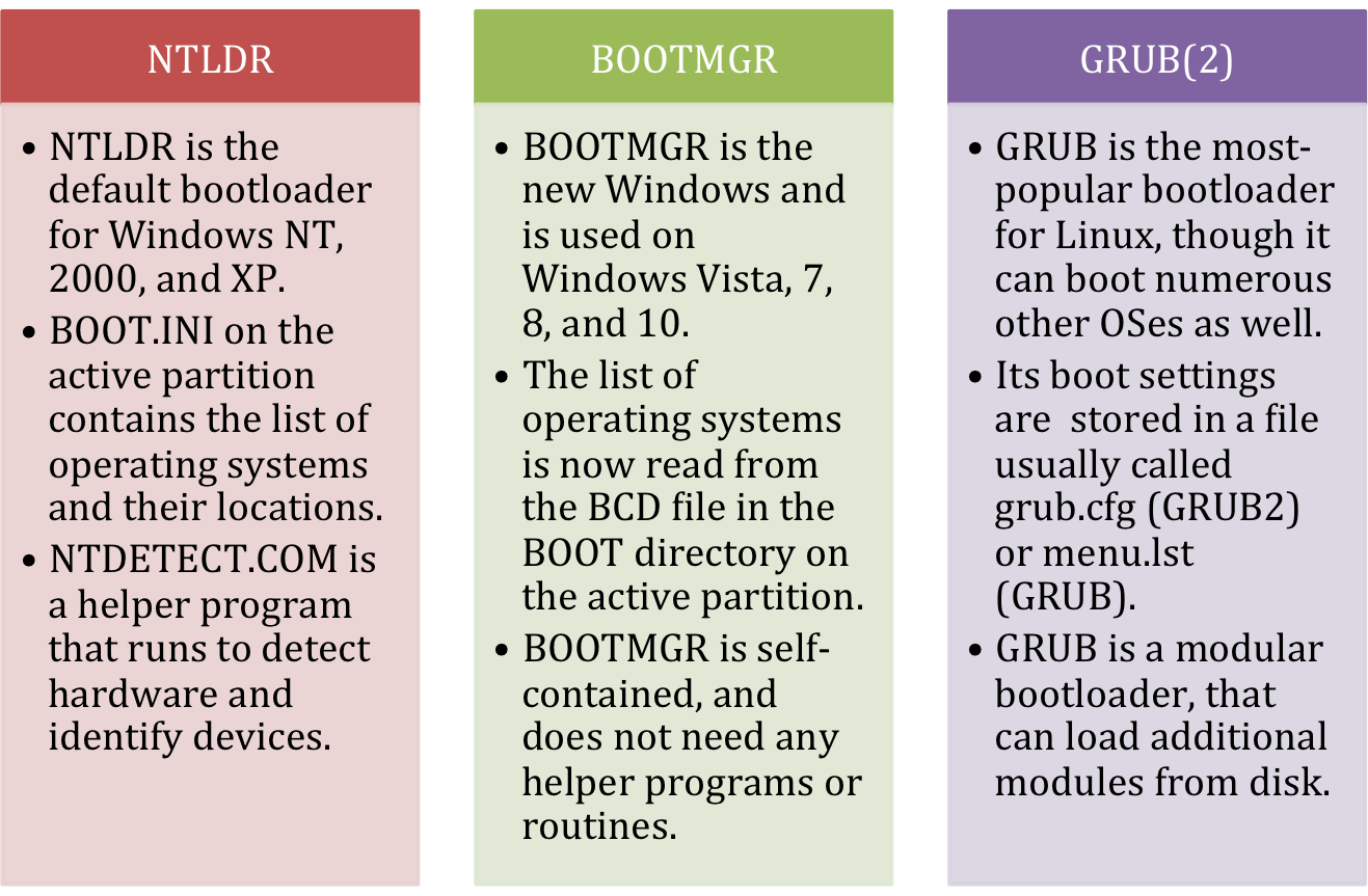
Each of the popular operating systems has its own default bootloader. Windows NT, 2000, and XP as well as Windows Server 2000 and Windows Server 2003 use the NTLDR bootloader. Windows Vista introduced the BOOTMGR bootloader, currently used by Windows Vista, 7, 8, and 10, as well as Windows Server 2008 and 2012. While a number of different bootloaders have existed for Linux over the years, the two predominant bootloaders were Lilo and GRUB, but now most Linux distributions have coalesced around the all-powerful GRUB2 bootloader.
NTLDR
NTLDR is the old Windows bootloader, first used in Windows NT (hence the “NT” in “NTLDR,” short for “NT Loader”), and currently used in Windows NT, Windows 2000, Windows XP, and Windows Server 2003.
NTLDR stores its boot configuration in a simple, text-based file called BOOT.INI, stored in the root directory of the active partition (often C:\Boot.ini). Once NTLDR is loaded and executed by the second-stage bootloader, it executes a helper program called NTDETECT.COM that identifies hardware and generates an index of information about the system. More information about NTLDR, BOOT.INI, and NTDETECT.COM can be found in the linked articles in our knowledgebase.
BOOTMGR
BOOTMGR is the newer version of the bootloader used by Microsoft Windows, and it was first introduced in the beta versions of Windows Vista (then Windows Codename Longhorn). It’s currently used in Windows Vista, Windows 7, Windows 8, Windows 8.1, and Windows 10, as well as Windows Server 2008 and Windows Server 2012.
BOOTMGR marked a significant departure from NTLDR. It is a self-contained bootloader with many more options, especially designed to be compatible with newer functionality in modern operating systems and designed with EFI and GPT in mind (though only certain versions of BOOTMGR support loading Windows from a GPT disk or in a UEFI/EFI configuration). Unlike NTLDR, BOOTMGR stores its configuration in a file called the BCD – short for Boot Configuration Database. Unlike BOOT.INI, the BCD file is a binary database that cannot be opened and edited by hand.8 Instead, specifically designed command-line tools like bcdedit.exe and more user-friendly GUI utilities such as EasyBCD must be used to read and modify the list of operating systems.
GRUB
GRUB was the predominantly-used bootloader for Linux in the 1990s and early 2000s, designed to load not just Linux, but any operating system implementing the open multiboot specification for its kernel. GRUB’s configuration file containing a whitespace-formatted list of operating systems was often called menu.lst or grub.lst, and found under the /boot/ or /boot/grub/ directory. As these values could be changed by recompiling GRUB with different options, different Linux distributions had this file located under different names in different directories.
GRUB 2
While GRUB eventually won out over Lilo and eLilo, it was replaced with GRUB 2 around 2002, and the old GRUB was officially renamed “Legacy GRUB.” Confusingly, GRUB 2 is now officially called GRUB, while the old GRUB has officially been relegated to the name of “Legacy GRUB,” but you’ll thankfully find most resources online referring to the newer incarnation of the GRUB bootloader as GRUB 2.
GRUB 2 is a powerful, modular bootloader more akin to an operating system than a bootloader. It can load dozens of different operating systems, and supports custom plugins (“modules”) to introduce more functionality and support complex boot procedures.
The actual bootloader file for GRUB 2 is not a file called GRUB2, but rather a file usually called core.img. Unlike Legacy GRUB, the GRUB 2 configuration file is more of a script and less of traditional configuration file. The grub.cfg file, normally located at /boot/grub/grub.cfg on the boot partition, bears resemblance to shell scripts and supports advanced concepts like functions. The core functionality of GRUB 2 is supplemented with modules, normally found in a subdirectory of the /boot/grub/ directory.
The Boot Process
As previously mentioned, the stage of the boot process is a little more involved than the previous steps, primarily due to the additional complexity of reading the filesystem. The bootloader must also obtain information about the underlying machine hardware (either via the BIOS or on its own) in order to correctly load the desired operating system from the correct partition and provide any additional files or data that might be needed. It must also read its own configuration file from a regular file stored on the boot partition’s filesystem, so it needs to at the very least have full read support for whatever filesystem it resides on.
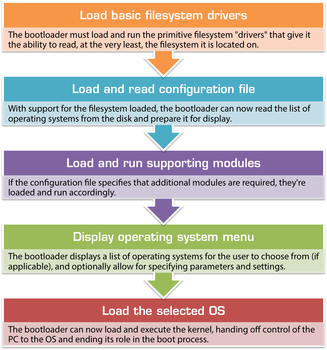
- Initiate filesystem access
Before anything else can happen, when the bootloader is first run it must load and run the primitive filesystem “drivers” that give it the ability to read, at the very least, the filesystem it is located on. Since it’s unable to read the filesystem before this, by necessity the code that provides this functionality must be compiled into the core bootloader file itself. - Load and read configuration file(s)
With support for the filesystem loaded, the bootloader can now read the list of operating systems from the disk and the the event that there are multiple operating systems specified, prepare it for display. - Load and run supporting modules
For bootloaders that are not wholly self-contained (such as NTLDR and GRUB 2), the bootloader now loads any supporting modules or helper programs (such as NTDETECT.COM) from the disk. The list of modules to load can be specified in the configuration file that was just read or hard-coded/compiled into the bootloader itself. Normally, each module will be executed as it is located and loaded from the disk. - Display the boot menu
At this point, with all the relevant configuration in hand, the bootloader can display what is commonly known as the boot menu on the screen. If multiple operating systems are installed, it is via the boot menu that the user of the computer can navigate a list of operating systems and choose which to load. From here, certain bootloaders also make it possible to specify run-time options, such as whether to load the selected operating system in safe mode. - Load the OS kernel
Once the user’s selection has been recorded, the bootloader moves on to the last and final stage of the boot process. Depending on the OS and the type of kernel, the bootloader will load the kernel image from the path specified in the configuration file (with the help of any submodules, if needed) into the memory. It then instructs the CPU to JMP to a certain location within the newly-loaded kernel and begin executing from there.
Conclusion
Thus ends the lengthy journey that begins with the push of a button and ends with an operating system’s kernel loaded into the memory and executed. The bootloader process is certainly a lot more nuanced and complicated than most realize, and it has both been designed and evolved to work in a fairly-standardized fashion across different platforms and under a variety of operating systems.
The individual components of the bootloader are, by and large, self-sufficient and self-contained. They can be swapped out individually without affecting the whole, meaning you can add disks and boot from different devices without worrying about upsetting existing configurations and operating systems. It also means that instead of having one, single bit of hardware/software to configure, setup, maintain, and debug, you instead are left with a intricate and oftentimes very fragile chain with multiple points susceptible to breakage and failure. When working properly, the boot process is a well-oiled machine, but when disaster strikes, it can be a very difficult process to understand and debug.
Troubleshooting the Bootloader
The complicated nature of the boot process means that there’s a lot that needs to be set up and configured, and a lot that could potentially go wrong. Some resources that can come handy when troubleshooting the bootloader are listed below:
- Easy Recovery Essentials for Windows: a point-and-click bootable recovery CD that will recreate the entire above-described boot chain to get you back into Windows pretty much no matter what went wrong.
- EasyBCD: An easy-to-use utility that allows you to set up and configure a dual-boot or multi-boot between Windows, Linux, Mac, FreeBSD, and more.
- Super GRUB2 Disk: A bootable GRUB2 disk that can be used to boot into Linux when your GRUB or GRUB2 is misconfigured or malfunctioning.
See Also
These additional articles and resources in our wiki and from other websites online contain additional information relevant to this topic:
- The EFI/GPT boot process: this document covered the basics of the BIOS/MBR boot process, now read and learn about how newer PCs with UEFI and GPT boot.
- The differences between EFI/GPT and BIOS/MBR
-
Originally, the BIOS was stored on what was termed a ROM (“read-only memory”) chip: the BIOS code was hard-coded into the chip and could never be changed. Updates to the BIOS were rare and far in between, and could only be done by physically replacing the BIOS chip on the motherboard. Over time and with better technology, erasable ROM chips were developed that could be cleared by placing them in a box and blasting them with a dosage of UV (ultraviolet) radiation, then reprogramming their contents with ROM chip programming hardware. When that got old and tiring, electrically-erasable programmable ROM (EEPROM for short) was developed – with it, an electronic signal on specially-selected pins of the EEPROM chip would trigger an erase, and the chip could be programmed directly from where it was located on the motherboard. Easy-peasy-lemon-squeezy, as my wife would say!! ↩
-
Almost every major hardware component now has firmware controlling it baked into its logic hardware, but we’re ignoring microcontroller firmware here. ↩
-
Depending on the operating system and platform, the bootstrap code might actually only be anywhere from 434 to 446 bytes as parts of that region might be set aside for other purposes, such as the disk signature and disk timestamp. On most modern operating systems, 440 is the upper limit as the last 6 bytes are set aside for the 4-byte disk signature at offset 0x01B8 and a 2-byte field indicating the read-write state of the drive at offset 0x01BC (with 0x00 indicating read-write and 0x5A5A indicating a read-only drive). ↩
-
There is a huge caveat emptor here: the bootable/active flag is actually a property of the individual (one of four) partition record, and not the partition table (list of partition records) or the MBR itself. What that means is that technically the actual bit indicating that a partition is bootable can actually be present (set to a value of 0x80) one more than one (or all!) partition(s) simultaneously! This is an invalid configuration and can cause many different boot problems though! ↩
-
On a little-endian machine like all x86 CPUs, that would be a single word 0xAA55 while on a big-endian architecture like PowerPC, it would be read and written as 0x55AA. ↩
-
Assembly is the most primitive programming language, and consists of individual instructions directly read and executed by the CPU. ↩
-
On NTFS, this is called the master file table, or MFT for short. On FAT32, this is called the FAT (file allocation table). ↩
-
In fact, the BCD file is a standard Windows registry hive, and it can be mounted for editing with tools like regedit.exe. ↩